Monday, May 5, 2014


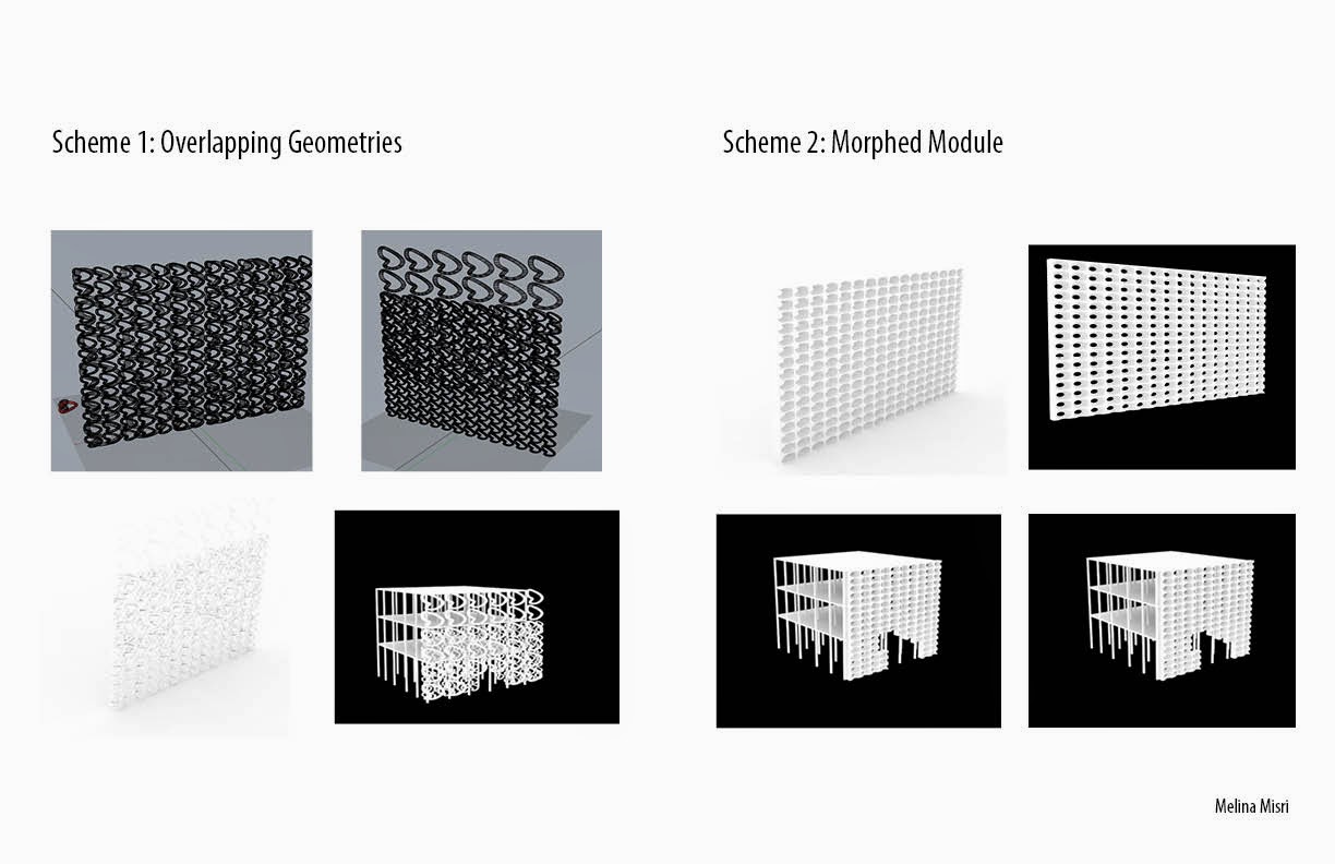
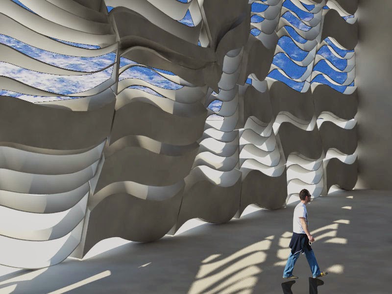
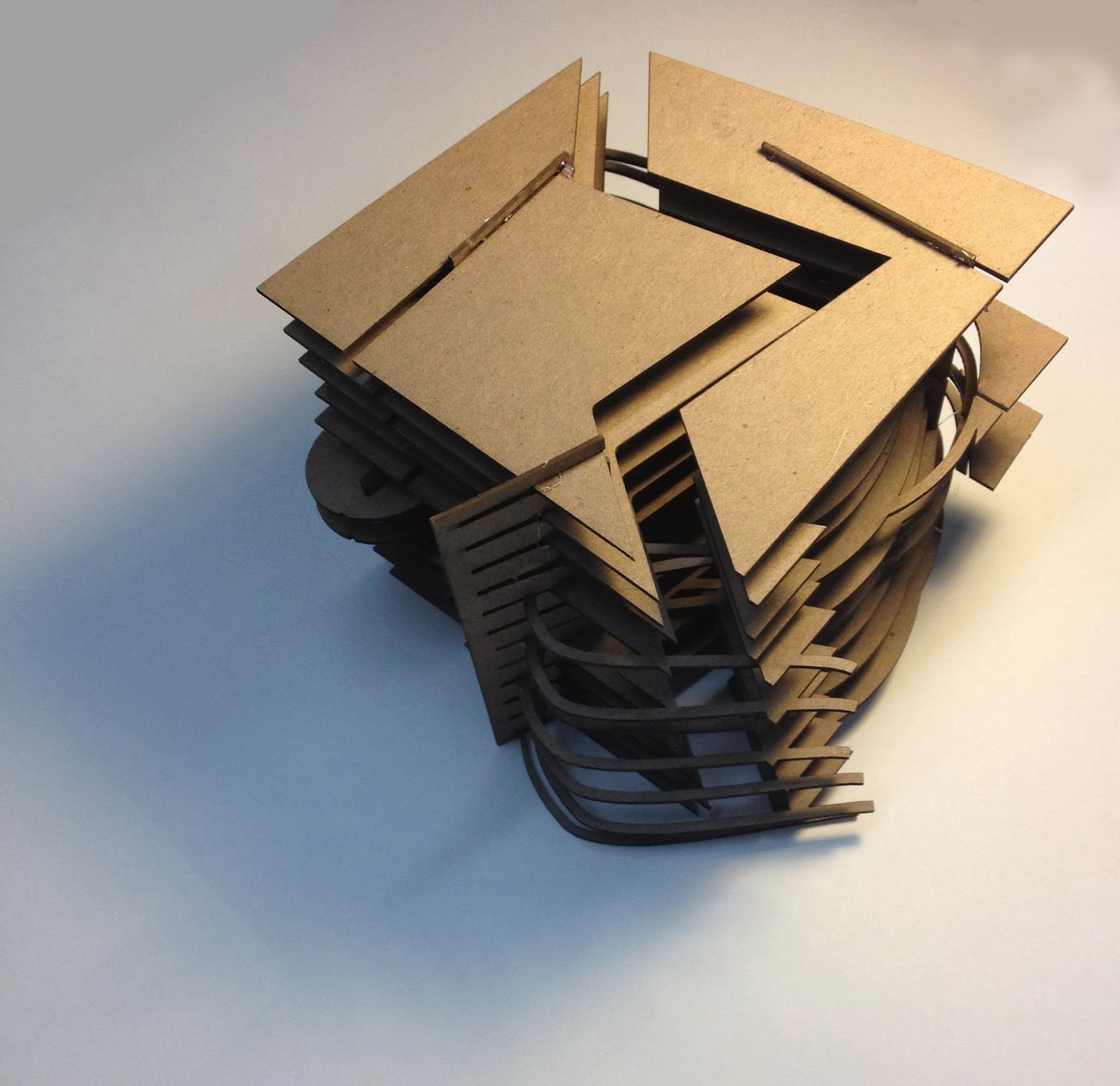
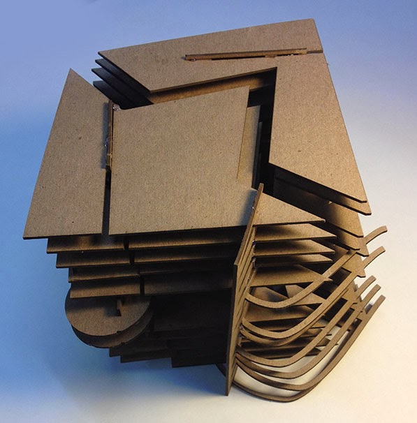
For my initial ideas for the final project, I decided to take two ideas I explored in the previous Grasshopper paneling exercise. First, I looked into taking a shape or module, creating a gradient in size, and overlapping the various gradients to create an effect in porosity and aperture. The second idea I looked into was taking a simple module and creating a morphed opening in order to vary the sunlighting results. I am still experimenting with creating a more fluid transition between the overlapping geometries, as well as faceting the morphed modules in order to show expressions of movement.

Grasshopper Paneling Systems


For this exercise, I was very interested in seeing how thicknesses in the module/geometry affected how the different shapes meshed together when transformed into a surface. I explored these controls using the V-Count and the size of the shape of the module in order to yield various results. As expected, the middle ground between an appropriate V-Count and module size showed the most legible and expressive results. However, I came across a "happy accident", in which I got the shape I made to overlap itself in a gradient that was applied to the surface, and I chose to explore this idea further for my final project (top row, 4th image).

Friday, March 28, 2014

Assignment 3

For my project 3 paneling exercise and rendering, I got my inspiration from a block of Ramen noodles, and examined how a single repetitive shape (the noodle) created varied shapes and sizes in voids. I created a paneling grid of a wavy shape that I then repeated to create the textured 3D panel. After deleting multiple panels, I was interested in seeing the different shadows that would be casted from these repetitive shapes, and looking at how the voids and shadows would come out differently. I was happy with the result of the pieces of sunlight that shine into the space, because although they do show some resemblance to each other, they are still, to some extent, irregular and varied from each other. I studied these voids in the vertical band on the left side of my board, in which I took a picture of Ramen, put it into Illustrator, and took the contour lines of the voids. I applied them to the side of the board as a subtle reference to the shapes of the voids found in a block of Ramen.

Monday, March 17, 2014

March 12 In-Class Activity


For the in class activity on March 12, we learned ways in which to fix renderings on Photoshop, as well as create daylighting in Rhino models using V-Ray applications. First we created a cube which had one side with a mesh pattern, and deleted fragments of the mesh pattern in order to create space for daylight to come through once we applied that visual effect. I struggled to keep up with the different effects we had to apply, but the end result is above. Learning how to create the effects on Photoshop was most interesting to me, because it was very new. I felt that the different V-Ray applications we used on our sample models are variations of what we have been doing throughout the semester (although they are much more complicated), but the Photoshop segment of the lecture really showed drastic changes and exemplified just how much more you can add to a rendering with simple tools. 

Tuesday, March 11, 2014


From top to bottom, I started by creating three curvilinear enclosed surfaces. I used the given commands in order to create the gridded outline seen in pictures 2-5. I then experimented with creating surface patterns that are pre-determined in Rhino, but I found their geometries to be somewhat boring (picture 6-9). I then began to create my own shapes and turn them into grids, and then applying them to the surfaces of these curvilinear shapes. I mainly changed the spacings between the points on the grid in order to see what the different outcomes were. Some of them turned out to be very interesting and create successful patterns, other created fragmented patterns, breaking the fluidity there was to the curves. Additionally, I noticed that the shapes I created in the 2D grids got warped when I made them into 2D surfaces and applied them to the curves. When I moved onto the 3D surfaces, I noticed that the shapes I created were less modified. However, one of the aspects I wish I had figured out how to control was the wall thickness when the 3D surface was created. I thought the patterns were much more difficult to understand and read in the 3D patterns than in the 2D patterns, however the 3D objects look more interesting and seem like they could be seen as some kind of day to day life object.

Saturday, March 8, 2014


After fixing my cube and gluing parts together, the model became much more legible and easier to understand. Because I did not use glue to assemble the model initially, many of the heavier pieces began to fall and slope, and some of the pieces which had been damaged from assembling and disassembling so many times got warped and began to slide around within the slits. However, I am much happier with the stable cube because every layer is now visible and much more interesting. 

Sunday, March 2, 2014


While completing the final cube project, I encountered various problems with creating the model. The structure was much more unstable than I anticipated and I had to end up changing the design slightly in order to add more supports. This involved going between Rhino, AutoCAD, and the laser cutting program in order to create the final product I was aiming for. Another problem I encountered was the warping of the chip board from the multiple times I had to assemble the model, which also caused me to have to go back and cut out more pieces. What I enjoyed most about this project was creating the board. I felt that I really got to apply what I have been learning over the past few weeks in class using Photoshop and Illustrator to create the diagrams and layout for my spread. I used different effects and tools to create a blended look between the V-Ray file and the Illustrator file, and explored different tools on these programs. 

Monday, February 24, 2014

A02 Progress Work


During today's class, I began to create the brackets which will hold my cube together. I realized that this would be the best way to go about assembling the cube, because with the waffling technique, the curve that runs through the middle of the break would disappear, and a large portion of my design would go unrecognized.

Sunday, February 23, 2014

A02: Cube Transformation Progress


In this iteration, I explored creating solids and voids, and seeing how they switch back and forth within the cube's templates. This came from only contouring the cube once, and after contouring in a second direction, I decided to revert back to the original single-direction contour because I was interested in the shapes that were created. The slow progression and growth in voids as they expand becomes more visible in the later phases of the cube, though there is always alternation between solid and void, and the different layers create a pattern of void morphing into solid, and back.
The rendering I created highlights the curve that runs through the entirety of the cube, as well as the schism between the two halves of the cube. I picked this angle because it highlighted how the curve extrudes from the surface as the progression from top to bottom continues, and it is emphasized by the division running through the center.

Wednesday, February 12, 2014

Through this project, I learned how to use the different command functions on Rhino, and got a good grasp on various manipulations that could be done using Illustrator. Through editing line weights (contours as well as hidden lines), my designs became more clear and consistent throughout my entire spread. Additionally, learning how to use color to further express ideas (addition and subtraction) makes the diagrams very visually appealing  and easy to read. Plans and elevations were taken from several angles, allowing for the cube to read throughout all it's facades. However, what I struggled with most was creating the void spaces. Because my cube had too many planes and cut-outs, the Boolean Difference option failed through various attempts. I resolved this by extracting the wire frame of the cube, turning the curves into surfaces, and extracting them to highlight the different voids seen in my cube design.

Monday, February 3, 2014

A02


Because this was my first time using Rhino and Illustrator, this project became challenging as it progressed. I felt that I understood how to use Rhino after a tutorial in class and after exploring it on my own, I started to discover features that I now feel comfortable doing, though there are still many techniques that I am interested in further learning. What I struggled the most with was transferring everything into Illustrator, and creating the line weights from there. I explored certain controls such as white vs. black arrows and their effects on what is being manipulated. As a further challenge, I practiced InDesign by making my rough layout on a new document and also exploring shortcuts and commands. Through this project I was able to begin to understand how to use certain features in photo editing to my advantage, in computer programs (and eventually hand drawings).